Modbus Configuration
HCC2 Modbus TCP Server Configuration
A HCC2 Modbus Server instance must be configured to map all HCC2 data points that an application needs to the appropriate Modbus registers.
The Modbus Server is configured through the HCC2 Unity interface. Instructions for configuring the HCC2 Modbus Server is outside the scope of this document. See the HCC2 software user manual in external references for more information.
The Modbus Server register map can be configured using the Modbus Map Editor accessed from the Deploy/Protocols/Modbus section of Unity Edge.
With the Modbus Map Editor, you can add HCC2 data points to your map using the data point/Tag Browser. You can mark registers as read-only or read-write.
Danger
Do not attempt to write to internal system data points. Doing so could cause unpredictable behavior and interfere with HCC2 operation.
You can also create "User Tags" for storing your own information. To do this, in the Tag Name column, select the ConstructFromMnemonic option and enter a tag name in the Tag Mnemonic box. Ensure you select the appropriate Register Data Type and Tag Data Type. Assign a meaningful name to the tag in the "User Defined Register Name" column:

The Modbus Map Editor will create a PDEF (Protocol Definition) file that can be downloaded from the menu at the top of the editor and deployed to the HCC2.
Tip
If you have created "user" data points, the download option will raise a warning that the data point does not exist. You can ignore this warning as the data point will be created when the PDEF file is deployed.
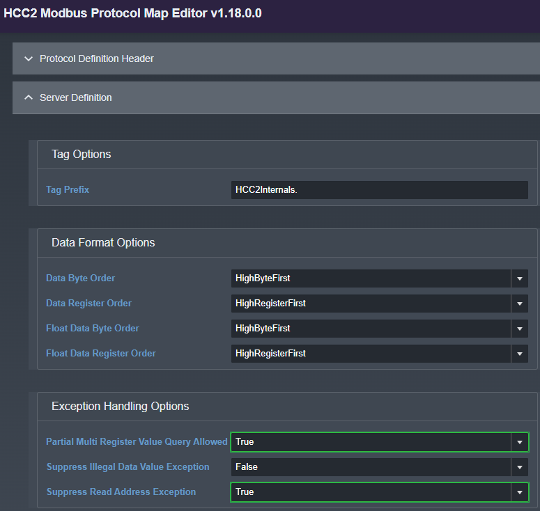
If there are gaps or non-contiguous addresses in the Modbus map, set two Exception Handling Option flags to True in the Map Editor under the Server Definition section, as shown. Then, download and apply the resulting PDEF file to the Modbus server after making the change:

Application Modbus TCP Client Configuration
The Modbus TCP Client (residing inside the application) must be configured to match the HCC2 Modbus Server configuration.
Modbus Client Configuration
To configure the Modbus TCP Client, perform the following steps:
- On your Development environment, go to directory
$HOME/edgesdkexample/config. -
Edit the file
config.json.A portion of this file is shown below. Modify as required:
{
    "version": "0.0.0",                     # your app version
    "variable_file": "config/vars.json",    # name of the vars config file
    "app": {
        "server_default_host": "localhost", # Address of the target Modbus Server
        "server_default_port": 502,         # Port of the target Modbus Server
        "server_default_unit" : 1,          # Modbus Slave Unit Number
        "default_time_period" : 1000,       # Time between polls (ms)
        "default_control_time_period": 100, # Time between writebacks (ms)
        "default_timeout": 0.6,             # Modbus Server response timeout (ms)
        "default_retries": 0                # number of retries
    }
For C#, the
config.jsonfile is:{ "Host": "192.168.X.X", # Address of the target Modbus Server "Port": 502, # Port of the target Modbus Server "SlaveID": 1, # Modbus Server Id "TimeBetweenPolls": 1000, # Time between polls (ms) "TimeBetweenControls": 1000, # Time between writebacks (ms) "Timeout": 2000, # Modbus Server response timeout (ms) "Retries": 0 # number of retriesImportant
Inline comments are for reference only and should not be included in your
config.jsonfile.
Variable Configuration
To configure the Modbus TCP Client variable configuration, perform the following steps:
- On your Development VM Machine, go to the directory
$HOME/edgesdkexample/config. -
Edit the file
vars.jsonto configure the application input and output variables. There are four types of variables: Input_status, Holding_registers, Input_registers, and Coils. You need to create one variable per register configured at the Modbus TCP Server level.The basic configuration of a variable is as follows:
"Input_registers": [
{
    "name": "input_var1",
    "collection_size": 1,
    "type": "float",
    "register_number": 0,
    "num_registers": 2,
    "writable": false,
    "word_swap": false,
    "byte_swap": false
},
…
]
where:
Parameter Description Input registersThe type of register to be used for this variable. In this example, it is Modbus input register type. Options include:
+ "Input_status"
+ "Coils"
+ "Input_registers"
+ "Holding_registers"nameThe name of the variable as used by the application. collection_sizeThe number of values to read for this variable. If greater than 1, the tag returned from get_value will contain an indexable array in the valuevariable; otherwise it will return a single variable.typeThe type of variable. Options are “boolean,” “integer,” and “float”. register_numberThe register number of this variable as defined in the Modbus Server configuration. num_registersThe number of consecutive registers that contains this variable. writableFlag indicating if this variable will be read-only (false) or read-write (true). Use true for output (writeback) registers. word_swapIf it is required to swap 16-bit words of a 32-bit integer or float. byte_swapIf it is required to two swap bytes in the 16-bit words.
You should create these types of blocks for each tag required by the application for each Modbus Data type.
Refer to the vars.json file in the example application for the full structure of this file.
Tip
Use the Live Data page in the HCC2 to filter and locate your tags and their values. To locate all tags on a particular Modbus link, filter on the Server Tag ID defined in Deploy/Modbus.